Clipping in DraftSight 2018


In today’s blog, we are going to talk about Clipping, specifically clipping References or Xrefs as they’re otherwise known as. That all sounds great, but just what exactly is clipping I hear you ask, well let me explain!
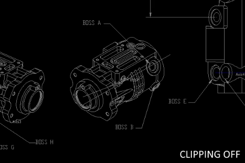
Basically, the Clip command allows you to create a boundary around an area in your Reference file or Underlay and only display what is inside that boundary. In the example below, you can see the difference clipping can make.
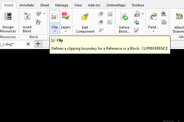
So, where can I find this command? Well, look on the Insert tab in the menu and under Reference section, you’ll see Clip.
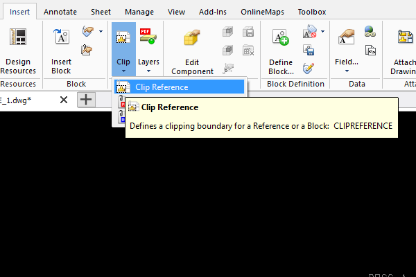
So, click on the Clip icon and from the drop down menu, select Clip Reference.
You’ll be asked to select the Reference you’d like to clip, so just click on the Xref and hit Enter. You’ll see a list of options in the Command Window.
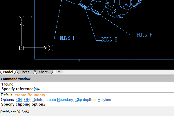
You’ll be prompted to select your Reference, so click on your Xref and hit Enter. You’ll then see various options in the Command Window.
Those options are:
- Boundary: Creates a new clipping boundary. If a clipping boundary already exists for the Reference or Block, you are prompted to delete the old boundary. Specify options:
- Invert clip: Lets you invert the display of the clipping boundary. Use the option to display the entities outside the boundary or to return to the previous mode.
– Polygonal: Lets you define an irregular polygonal shape as clipping boundary by specifying points.
– Rectangular: Lets you define a rectangular clipping boundary by specifying two opposite points.
– Select polyline: Lets you select an existing PolyLine to serve as clipping boundary. Arc segments are decurved. - Clip depth (used for 3D clipped References or Blocks): Sets the front and back planes parallel to the clipping boundary. You select the planes by specifying clip points. Use inferencing to select geometry. Specify options:
– Distance: Uses specified distances from the clipping boundary to create the front and back planes.
– Remove: Removes the clipping planes. - Delete: Removes the clipping boundary.
- Off: Turns the clipping boundary off to display the Reference or Block entirely. The clipping boundary is retained so you can activate it again.
- On: Turns the clipping boundary on to display only the portion of the Reference or Block inside the clipping boundary.
- Polyline: Creates a PolyLine from the clipping boundary you created before (using the Rectangle and Polygonal options).
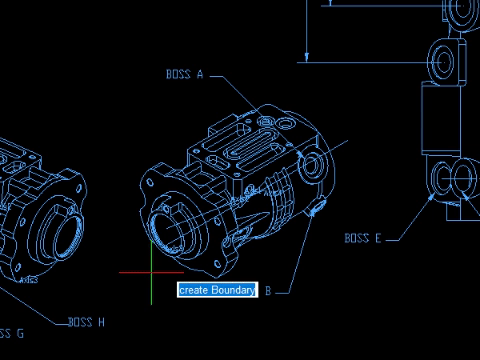
The default option, Create Boundary, is automatically selected. Just click Enter. The default option is Rectangle, but depending on what you want to clip, you can switch to Polygonal or, if there is a Polyline surrounding the area, you can select it instead.
In our example, I’m going to select Polygonal. I then select points around the area I want to clip and once I have draw a Polygon around the area, I hit Enter and the area is clipped!
That’s it, that’s a simple breakdown of how to use the Clipping command in DraftSight Professional 2018. As always, check out the in-built Draftsight Help file for more information on the command.
Learn more about DraftSight 2018 here.
Purchase DraftSight Professional 2018 for as low as $149 here.
Latest posts by MJ Smyth (see all)
- Resetting DraftSight to Default Settings - April 12, 2021
- Associative Patterns in DraftSight 2021 - March 24, 2021
- DraftSight 2021 SP0 Now Available - March 3, 2021