Electrical Drafting in DraftSight


Well over 50 percent of the CAD work I do in DraftSight is electrical related. That’s everything from Lighting, Data and Power Layouts to Board Schematics. Over the years, I’ve created and downloaded many blocks for my Electrical Library. Some I’ve edited to suit, others were perfect the way they were.
Electrical drawings are very dependent on legends. Every electrical drawing I create, has an Electrical Legend on the drawing so there can be no mistaking a fitting for something else.
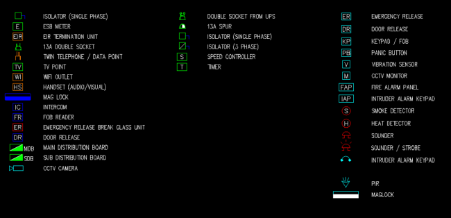
Those symbols do not change. From project to project, a 13A Double Socket always looks the same, it does not deviate. However, depending on the project, new symbols are often created. For example, the Double Socket from UPS, whilst still similar to the original, is different. You know it’s a Double Socket, but you know it is non standard.
Likewise, there are specific Electrical Layers, these also do not change from project.
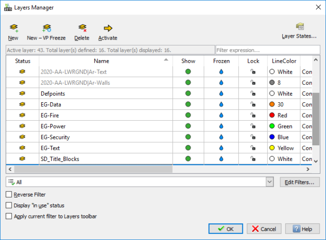
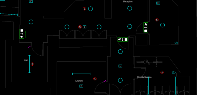
So, Data entities will always be found on EG-Data, Fire on EG-Fire and so on. I think you get the idea! All blocks are created with the colour set to Bylayer, that way, it’s easy to tell if you’ve accidentally placed a block on the wrong layer. Lighting Drawings are no different. Each entity type, Light Fittings, Wiring, Emergency Lighting and so on all have their own individual layers. Again, these blocks stay the same from project to project. You’re not trying to give an accurate representation of the fittings used, just an accurate location for them to be installed.
The last type of drawing I do on the Electrical side of things are the Electrical Schematics. These could be for Fire Alarm, Electrical Boards or just a general overall Electrical Schematic. Again, these are created using my block library. It’s very important, when drawing Electrical Schematics, to have a good sense of space on your Title Sheet. I’ve often seen users create beautiful schematics, but when they go to put a title sheet on them, it doesn’t fit. The first thing they decide to do is to shrink the schematic itself, but that leads to smaller text and smaller symbols, making it harder for the contractor to read. That is a really bad idea! If the contractor can’t read your drawings, then you are increasing the chances of a mistake on site. The only option left is to tweak your schematic to fit, a little stretch here and there, move a board around, move some text… It’s all time consuming stuff.
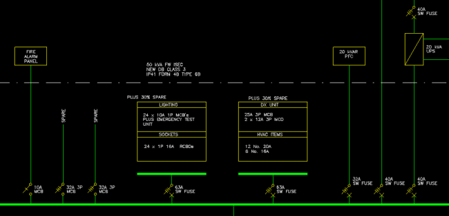
So, what do you do? Well, take some time before you draw the schematic to plan it out. Just roughly sketch it out on a sheet of paper and go from there. It might take you 20 minutes, but it’s better than a few hours at the end of the project!
And that’s a brief rundown on how I use DraftSight for Electrical Drafting. The great thing about DraftSight is its flexibility. You can use it to draw anything you want. Unlike some other CAD packages, it is not tied to just one discipline.
Read a customer story on how Innovative Manufacturing Services creates schematic layouts for their electrical panels with DraftSight.
Learn more about DraftSight here.

Latest posts by MJ Smyth (see all)
- Resetting DraftSight to Default Settings - April 12, 2021
- Associative Patterns in DraftSight 2021 - March 24, 2021
- DraftSight 2021 SP0 Now Available - March 3, 2021