Landscape Architecture: Create a Planting Plan in DraftSight


Creating a landscape architecture planting plan is a routine task for landscape architects and designers, but the way you draft it can make a big difference. When you’re adjusting bed lines, swapping tree types, or re-labeling species across a large site, small efficiencies add up. DraftSight helps keep those tasks moving without getting in the way. This blog shows you how to create clear, editable planting plans using familiar CAD tools that support accuracy and efficiency.

What is a Landscape Planting Plan
A landscape architecture planting plan is a 2D drawing that outlines the placement of plants, trees, and shrubs within a design. These plans typically include symbols, labels, and patterns that identify each type of plant, allowing you to effectively communicate your planting design and landscape architecture decisions to clients and installation teams.
Why Use DraftSight for Planting Design
DraftSight keeps the drafting process efficient and familiar. When designing with plants, you can draw precise bed lines, build and reuse tree plan CAD blocks, and label plant groups clearly, all using tools that behave the way you’d expect. It’s well-suited for plant CAD work because it handles complexity without overcomplicating the interface or the workflow.
Step-by-Step Guide to Creating a Landscape Architecture Planting Plan in DraftSight
Draw Planting Bed Lines:
Start by drawing the lines of the planting bed. These lines define where each type of vegetation will be placed. In DraftSight, you can use the LINE or POLYLINE commands, depending on whether you’re drawing individual lines or connected shapes. These bed lines give your drawing structure and help define areas for trees, shrubs, or groundcover.
Fill in the Planting Beds with a Pattern:
Once the beds are drawn, it helps to fill them in with patterns to indicate different plant types. You can use the HATCH command to do this. Select a hatch pattern that suits your design, click on the bed outline, adjust the scale as needed, and apply it. Using different patterns for different plant groupings makes your plan easier to read and more visually organized.
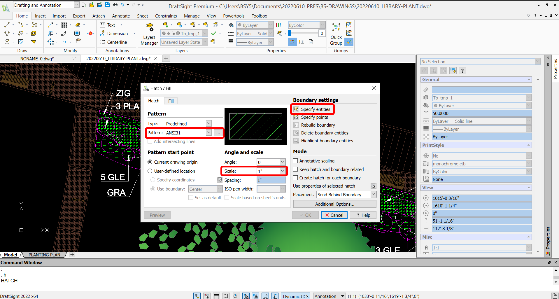
- Type HATCH (“H”)
- Select a pattern to fill in your planting beds
- Select the boundaries of where you want to hatch
- Adjust the scale of the pattern
- Click OK and the pattern will be filled in the area selected
Making Tree CAD Blocks:
To add trees or other plants that repeat across the plan, it’s a good idea to turn them into blocks. After drawing your tree symbol, select all its parts and create a block using the BLOCK command. Give it a name and choose a base point. Now, every time you place that block, it remains consistent, and if you ever need to edit it, you can update all instances simultaneously.
- Draw your tree
- Select all the lines of your tree that you want to make into a block
- Type BLOCK or MAKEBLOCK (“B”)
- Give the block a name
- Choose a base point for your block
- Click OK and the block will be created
Creating Dynamic Blocks:
Dynamic blocks add flexibility by letting you switch between different versions of a symbol, like showing several tree types from a single block. To set this up, open the block in the editor, add visibility controls, and define each variation. You’ll be able to toggle between versions without having to redraw.
- Create one tree block (see previous Making Tree Blocks)
- Then double-click on the block to bring it in to editing mode
- In the EDIT BLOCK tab, in the ELEMENTS section, click on the POINT dropdown, and select VISIBILITY
- Choose the base point of the new block/visibility state, hit enter, and type “1” (this creates the drop-down arrow so that you can select which block to be shown)
- In the DISPLAY STATE section at the top, click on VISIBILITY STATES…
- Click on +New…
- Type in a name for the new Visibility State/Block and select “Hide all existing entities in new state.”
- Click OK and now insert a new tree block to be added to the Dynamic Block
- In the SAVE section at the top-left, click on SAVE
- In the CLOSE section at the top-right, click on CLOSE
- Now click on the drop-down arrow to select which block you want to view in the plan
Labeling Plants (using the multileader tool):
Once your plants are in place, the next step is labeling. The multileader tool in DraftSight makes this easy. Just click to place the arrowhead, and then click again to set the text location. Enter your plant name or code and adjust the scale as needed. This keeps the landscape architecture plan drawing clear and concise.
- Under the ANNOTATE tab, click on INSERT in the MULTILEADER section.
- Click on the screen where you want the arrowhead to be placed, and then click a second time where you want the text to be placed.
- Type in any text you want to be shown
- Adjust the scale as needed in the properties on the right
Interested in learning more?
Visit our dedicated Landscape Architecture page. You can also read the other blogs in the Landscape Architecture series, Landscape Architecture How-To: Image Tracer for Landscape Architects/Designers and Landscape Architecture How-To: Setting Up Sheet Sets in DraftSight.
See how DraftSight can support your landscape architecture projects. Try DraftSight Premium for free for 30 days.

Latest posts by DraftSight (see all)
- Shanghai International Circuit: The Geometry Behind the Chinese Grand Prix - March 13, 2026
- Engineering Precision: Melbourne’s Grand Prix Circuit with DraftSight - March 6, 2026
- When DraftSight Needs a Fresh Start: How to Reset to Default Settings - February 4, 2026