Understanding Broken-Out Sections in Technical Drawings
Sometimes, you don’t need to see the whole interior of a part or building to understand what work needs to be done. This is where having the ability to view various sections comes in handy.
Section views are a very important technique in design and documentation. They reveal the interior features of parts, improve the visualization and clarity of new designs, clarify multi-view drawings, and facilitate the dimensioning of drawings.
For mechanical drawings, section views are used to reveal interior features or components of an object when hidden lines do not properly represent them, such as when multiple interior features and excess hidden lines overlay each other.
Architectural drawings use section views to reveal the interior details of walls, ceilings, floors, and other elements of the building structure.

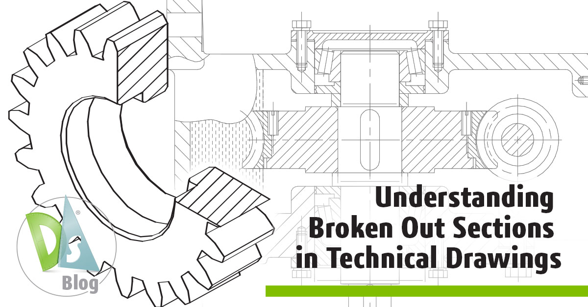
A primary reason for creating a section view is to eliminate hidden lines. Today, we want to talk about the benefits of a broken-out section view. Broken-out sections allow you to define a custom cut line to isolate specific details of a model in a section view by essentially “breaking out” a portion of the geometry to show more detail. A broken-out section is part of an existing drawing view and is not a separate view. A closed profile, usually a spline, defines the broken-out section, and material is removed to a specified depth to expose inner details. You can specify the depth by setting a number or selecting geometry in a drawing view.
Here are some other things to know about a broken-out sections:
- Cross-hatching: Cross-hatching is automatically generated on the sectioned faces of all components.
- Preview: A preview can be used to see the cut more clearly.
- Selection: The selection box can be activated instead of entering a numerical value.
- Exploded views: A broken-out section cannot be created on an exploded view that is collapsed.
The benefits of using a broken-out view include emphasizing specific features, reducing clutter, and improving clarity—all of which improve visualization overall.
Did you know you can create a broken-out section view in DraftSight? It’s a feature in SOLIDWORKS 3D modeling software and is also available in DraftSight.
To create a broken-out section view in DraftSight, you can use the Section tool, where you essentially create a standard section view but then sketch a closed profile within that section to define the area where you want it to break out and reveal internal details. This is typically done by selecting a parent view, then sketching the breakout area within the section view, and specifying the depth of the cut to expose the desired internal features.
Key steps:
- Select the parent view. Choose the existing 2D view where you want to create the broken out section.
- Access the Section tool. Navigate to the Drawing tab, then select the Section tool.
- Define the section line. Click and drag to define the cutting line for your section view.
- Enter sketch mode. Once the section view is created, click the Sketch button to enter sketch mode.
- Sketch the breakout area. Using the drawing tools, sketch a closed profile within the section view to indicate the area where you want it to break out and reveal internal details.
- Set the depth. Specify the depth of the breakout by selecting an edge on your model that defines how far the section should cut into the part.
Important things to note include:
- The area you sketch to create the breakout must be a closed loop (closed profile).
- Carefully select the edge to define the depth of the broken-out section.
- You can rotate or zoom the view to better visualize the broken-out section.
Many of the mainstream CAD tools have the option to create broken-out sections. Key features to look for in a broken-out section tool include.
Key features to look for in a broken-out section tool:
- Custom cut line creation: Ability to draw a closed profile (like a polyline or spline) to define the exact area of the model you want to isolate in the broken section.
- Depth control: Option to specify how deep the broken section should extend from the cut line, allowing you to control what part of the model is visible.
Preview functionality: A visual preview of the broken section before creating the final view, helping you adjust the cut line and depth as needed.
DraftSight is equipped to handle broken-out sections, enabling you to get a better look at internal key features and focus on fine details and specific areas and components you need to work on.
For more blogs on accuracy and clarity in detail drawings, check out these blogs:


